| My day gig |
| From "Stooge Larry’s 'Wise Guy' Synthesizer page" |
| http://www.wiseguysynth.com/larry/day.htm |
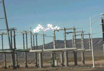 |
| The photo above will link you to an amazing video (~1.5 Mb) of a ½ million volt switch failing to interrupt the arc when operating. Special thanks to Old Crow for hosting this popular video. If you are interested in some light technical analysis of what you are looking at, see the text below this photo. |
|
When I am not messing around with modular synths or shipping parts for
synth builders around the world, I have a regular job. Like most
musicians, I call it my day gig. I have worked for an electric utility
company in the Midwest, USA for over 27 years. I am what is called a
"high-voltage specialist." So, while my synth circuit abilities are
somewhat limited, I am well versed in the operation of high voltage AC
circuits. I was not given the details of this
clip when it was sent to me. However, based on what I do know about the
equipment in the video and what I see, I offer the following info:
The file name Lugo suggests a large California substation that is
populated with 500 KV and 230 KV switching devices. This one is clearly a
500KV (I can tell by the size) three-phase switch, probably rated at about
2000 amps of normal current carrying capability. In this case, the switch is being used to connect a special kind of transformer. The 3 single-phase transformers can be seen behind the truck. I say transformer, but as you can see, they have leads going in, but not coming out. These are actually single winding inductors connected from phase to ground and are commonly called "shunt reactors." These inductors are installed to offset the capacitive effects of un-loaded transmission lines, When a long 500 KV or 765 KV line is energized from one end, its inherent capacitance causes an unacceptable voltage rise on the open end of the line. The "shunt reactor" is installed to control that open-circuit voltage. Where current into the capacitor component of the line impedance leads voltage by 90 degrees, current into the shunt reactor lags voltage by 90 degrees. The switch being opened is called a "circuit
switcher." It consists of two series SF6 gas puffer interrupters (kind of
like a circuit breaker) and an integrated center-break disconnect. The
interrupters are to the right of the switch blades. They just look like
gray porcelain insulators. At 345 and 500 KV these types of switches
typically have two interrupters per phase in series in order to withstand
the open circuit voltage encountered when de-energizing a line or
transformer. They rely on synchronized opening of the two interrupters and
voltage even distributed across the two interrupters by "grading" devices
(typically lots of series capacitors or resistors). |
|
I hope you enjoyed the show. |