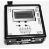
| H-Bridge Stress Tester (TES 1391) | |
 |
Schematic PWB Gerbers Hex File Source RS232 Manual (Command: $00FF[cr]) Typical settings for pots This circuit drives an H-Bridge from 5V, where 200 ohm pots on the top and bottom of each leg set the voltage and current delivered to the unit under test (UUT). At the end of each on period, the voltage across the resistance of the low side pot is measured and reported. If the UUT should suffer an increase in resistance or a complete open circuit where its current has fallen below a preset threshold, the testing will stop and the count of cycles at failure will be displayed. For each cycle, the on and off times for the positive and negative UUT half cycles can be programmed from 1 to 99mS for the on time and 0 to 99mS for the off time. When testing, to minimize processing time, the current cycle count and ADC readings are displayed and sent to the serial port in HEX. When testing has stopped the cycle count and last ADC reading are displayed in decimal. Timing and test threshold control variables are written by RS232 command and stored in EEPROM so once programmed the box can run tests stand-alone. Pressing both Start and Stop buttons at the same time for 5 and then 10 seconds displays the timing variables and then the test limits respectively. The ADC reading is from 0 to 1023 with a FSV of 2.5V, where the actual voltage on the bottom (Current sense) resistor is calculated by: Vsense = (ADC/1023) x 2.5. The pots may be connected to an Ohm meter and set at any time the UUT is disconnected and the test is not running, i.e. in stop mode while powered on. |