| B7971 SmartSocket redesign (TES 1386) | |
 |
B7971
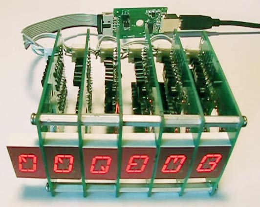
Schematic B7971 BOM B7971 Gerber Data PIC16F690 Image TES PWBs/Kits Socket Soldering Original Assembly Instructions In Circuit Programming The circuit created by Chris Barron (Yahoo group fixitsan2) covered under a generous license agreement has been redesigned in Proteus CADD. This B7971 14 segment nixie driver board was originally done in the Eagle PCB design program but needed a bit of cleanup for production PCBs to be ordered. |
  Movie |
The program written by Chris uses a protocol
which runs
over a 9600 baud daisy chained RS232 channel. Tx from the master
goes into the Rx of the first module, Tx from the first module goes into
the Rx of the second and so on. At power up, the first module sends
the number "1" to the second which sends the number "2" to the third and
so on which allows each module to know which portion of the transmitted
message it should act on. Because each character transmitted from
the master must be first read by the module in the chain before it can
proceed to the next module, the data will have a one character latency for
each module in the chain so that the data from the last module in a six
module chain will lag the original data from the master by six characters,
but this will have no practical consequence unless enough modules are
chained together to make the delay noticeable and would only produce a
sweeping effect as the new data over writes the old. These sequence of events can be seen in
the
timing of the RS232 data
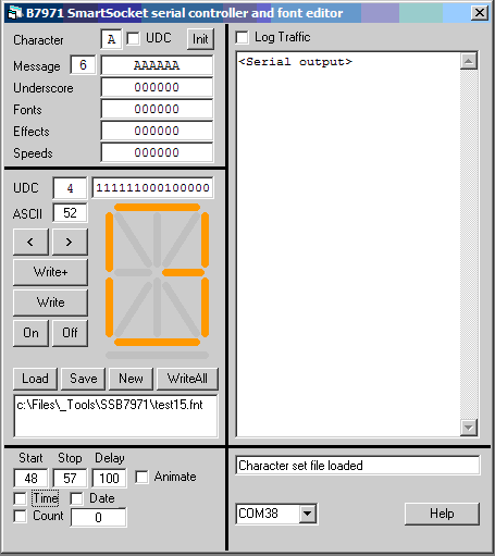
transmitted from each module. I have written a utility in the Calculators program in the <controllers><[1386] SmartSocket> menu to assist in writing and testing serial communication to smart socket strings. It also includes a font editor for the B7971 SmartSocket UDC (User Defined Character) feature. Not having any tubes myself, I had to build a test bed using LEDs to verify function and validity of the reformatted help texts which can be accessed with the GUI help button. To edit the font, click on the segments to turn them on and off or edit the bit pattern manually and the segments will follow. When done with a single character, hit "Write" and the pattern will be written to the socket(s) and displayed (Providing "U" is selected as the current font). An entire font set can be edited and then saved to file, loaded from a file or written at once to the socket(s). The animation and display buttons let you play through a sequence of characters to test the look and feel. The movie to the left shows various controls such as displaying the time, date, alphabet and effects. The initial time display uses a new 0-9 font that took about one minute to create, save and then write to the entire socket string. |